
Part Production Cell — MES & OEE
OpenPLC, Ignition Perspective and SQLite: order in events, KPIs and downtime causes.

This case is less about one HMI screen and more about a readable control loop. I worked through ladder conditions, Modbus TCP exchange, and the state an operator sees in Ignition.
I started with modes and interlocks in OpenPLC. Then connected Runtime to Ignition, checked addresses and tag quality, and only after that built the Perspective screen.
The goal was practical: follow a command from the operator to the process and back again. This is a training prototype, not a production or safety-certified system.



I started with what the PLC needs to decide. The ladder covers Auto and Manual, level thresholds, E-stop, and pump and outlet-valve interlocks. The point was to define which logic is allowed to send a command, not simply energise an output.

I started with two modes. In Auto, the PLC holds the level. In Manual, the operator sends a request, but the final command still goes through ladder logic.
The scenario is simple: the pump starts at 35% and stops at 70%. It shows basic level holding without a PID loop.
High-high blocks the pump. Low-low closes the valve. E-stop removes both commands. These limits apply in either mode.
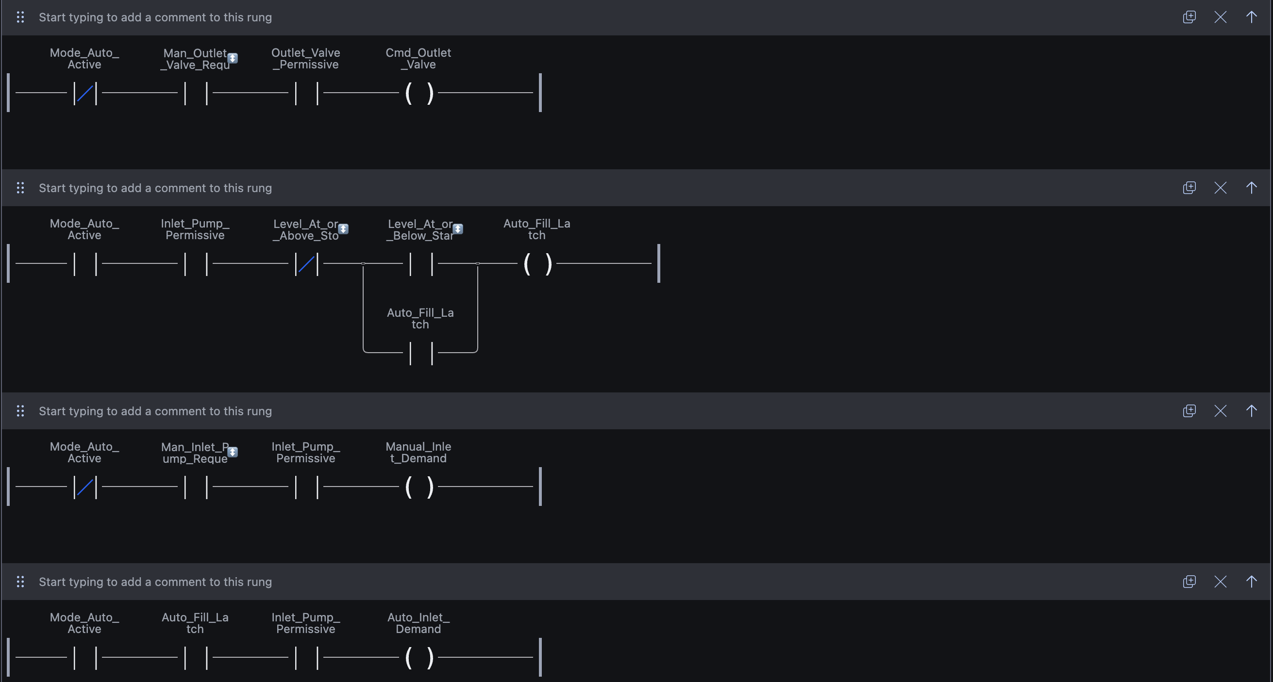
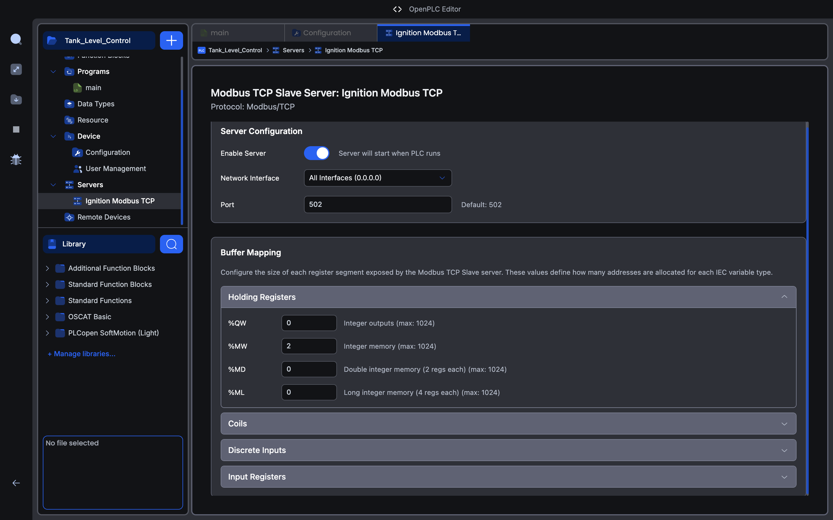
After the logic, I connected OpenPLC Runtime to Ignition through Modbus TCP. Every signal has a fixed address, type, and direction. Then I checked the chain step by step: PLC bit, OPC tag, Good quality, and only then HMI display.

Runtime exposes PLC memory to Ignition. After an upload, I checked that Modbus was active and port 502 was available.
Every signal has a fixed address, type, direction, and owner. This separates a connection problem from a tag writer conflict.
I checked one signal at a time: PLC bit, OPC tag, Good quality, HMI display. That way the interface does not hide a connection problem.
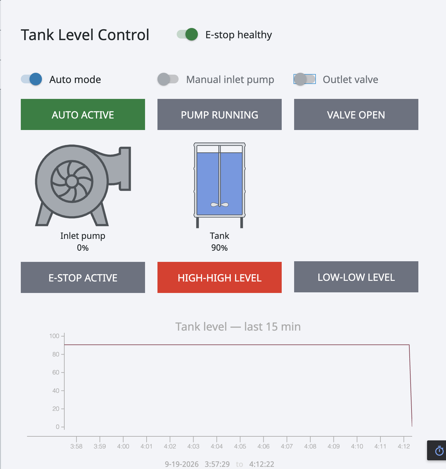
Once the exchange was stable, I built the operator screen in Perspective. It brings together modes, commands, level, equipment state, alarms, and a trend. The screen reads PLC state instead of storing its own version of it.

One screen brings together modes, commands, level, actual equipment state, and alarms. The HMI shows PLC data, not a local assumption about state.
The 15-minute trend shows what happens to level after a command. Polling keeps the realtime window moving.
I checked Auto-fill, manual commands, high-high, low-low, and E-stop. The point was not only the screen but the full signal path.
What this prototype demonstrates:
OpenPLC, Ignition Perspective and SQLite: order in events, KPIs and downtime causes.

OpenPLC and Ignition: ladder logic, a Structured Text state machine, sensor feedback, and verifiable normal cycles.

Enterprise monitoring for a nuclear plant: system states, engineering constraints, and 3D storage logic.